
How to make your own Open Source Microlight (OSM/OSM2) Programmer Cable
If you didn’t already know, this past year (2015), has been very good for anybody interested in microlights (gloving) because last year we saw the release of the brand new Open Source Microlight, thanks to the one and only Ramiro Montes De Oca. With the original OSM being so popular on Kickstarter, the release of the OSM2 was not far behind the original. So of course you know I had to pre-order a set of the OSM2 immediately once I found out … and thankfully Ramiro is very active on the OSM Mode Swap facebook group, and after shipping out the first set of OSM2’s, he let everyone know that there was going to be a slight delay on shipments as he ran out of programmers for them, but if you had one already, he could ship out your chips. Well … being the junkie and geek that I am, I didn’t want not having a programmer to stop me, so I set out on a mission to figure out how to build my own programmer, and here’s how I did it…
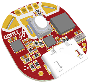
So after searching around, I was able to figure out some basic details about the programmers, and how to connect between your computer and the OSM chip. It’s basically an Arduino USB2Serial (USB to UART) with a Silcon Labs CP2102, using reset line connected to micro usb shield. In layman’s terms, the OSM/OSM2 chips can only talk using the standard serial communications, and if you’re old enough to remember when computers had serial ports, that is exactly what we’re using … except almost all computers/laptops nowadays, do not have serial ports anymore …. so what are we to do? Use a USB to Serial converter!
If you’re thinking … “wow that’s it?” … you’re correct. We’re not building a programmer to be compatible with the OSM/OSM2 chips … we’re building a programmer to make YOUR computer/laptop compatible with standard serial communications to the OSM/OSM2 chips, with one small caveat … we have to convert the serial communication lines to a micro USB cable, with the reset line (normally DTR) to the micro USB shield. So yes, the communication is standard serial, but the connector, and cable, are not standard.
Parts and Material
For parts and material you’re going to need at a minimum, some type of USB to UART converter (basically a USB to Serial converter). There are tons of them on the market, and the most popular is FTDI, but I (and Ramiro) do not recommend using FTDI since they screwed really badly with the Arduino community (google “FTDI gate”). Which is the reason he went with a Arduino2Serial solution in his programmers.
Required Material/Parts
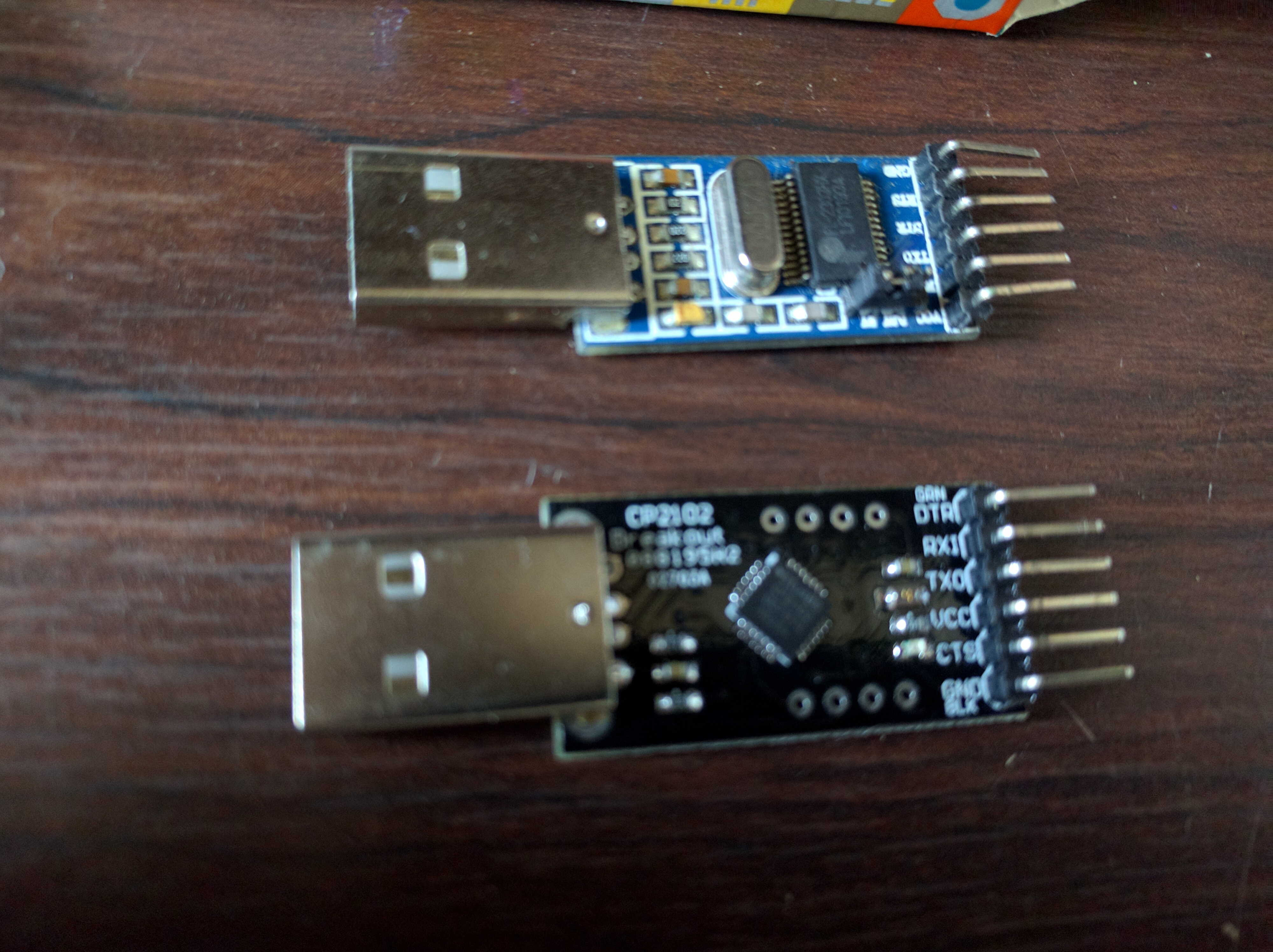
USB to UART Converters
- USB to Serial Converter (USB to UART) – Strongly Recommend CP2102
- ~$6.99 on Amazon:
http://amzn.com/B009T2ZR6W
http://amzn.com/B00NWHXCZI
- ~$6.99 on Amazon:
- Some wire, and a DIY Micro USB Connector (or salvage an old MicroUSB cable)
- ~$0.95 on Adafruit (buy a few in case you mess one up)
https://www.adafruit.com/products/1390
- ~$0.95 on Adafruit (buy a few in case you mess one up)
Optional (and Helpful) Material/Parts
- Soldering Iron (Needed if you purchase USB to Serial from above, see below for details)
- Multimeter
USB to Serial Overview
If you’re a geek like me you probably already have a USB to Serial converter of some sort, and you CAN use it, just make sure to match up all the pinouts correctly (and if you don’t have a reset line, you should be able to use DTR as long as it’s connected to IC, which normally is the case).
If you don’t, I strongly recommendation buying one with the CP2102 chip. Reason being is, the programmer that Ramiro sells uses this same exact chip, and thus, all the drivers referenced on the OSM website would be exactly what you need, and when you plug in the USB to Serial device, it will show up on your computer as /dev/cu.SLAB_USBtoUART (Mac OSX/Linux) and there are some additional firmwares out (Primer + Tekton, Vectr) there that specifically look at this path, which is basically just a virtual COM port.
Preparing the USB to Serial Device
So if you decide to purchase the CP2102 from above, the first thing we will need to do is to make a small solder connection on the back of the device to tell it to output 5v.
SORRY THIS GUIDE IS INCOMPLETE AT THIS TIME, I WILL TRY AND FINISH IT ASAP!
IN THE MEANTIME, CHECK OUT THE FULL TUTORIAL ON THE OSF FORUMS:
https://osf.guru/viewtopic.php?f=30&t=86
Related Posts


-
Logan Knowles
-
Myles McNamara
-