
How to build a reverse “mux” headphone splitter (2 inputs, 1 output)
So i’m sure you’ve seen those Y splitters you can purchase online that are used for instances where maybe you want to have two headphones hooked up to a phone or laptop…but what about when you want to have two outputs going to one input? You could in theory just hook it up in reverse, but then you are risking damaging those devices and i’m sure you don’t want to ruin something worth hundreds or thousands of dollars just to save a couple bucks. Say you want to have your laptop and desktop connected to your speakers…but the speakers only have one input, that’s the idea behind this…you can purchase switches out there that require you to manually change the input, but that wouldn’t work for me. So here’s how I built my own for only a couple bucks…
In simple terms, all we’re going to do is build our own splitter but for each input we are going to put a 1k resistor between the each channel (L & R) input and the output. Originally my thought was to use a standard diode which would only allow voltage in one direction but because the audio is going to be an AC voltage a diode will not work. You can use almost any standard resistor you may have 1k – 10k or so but keep in mind a 10k resistor will reduce the audio output volume a lot more than the 1k, if you have a 1k, use those.
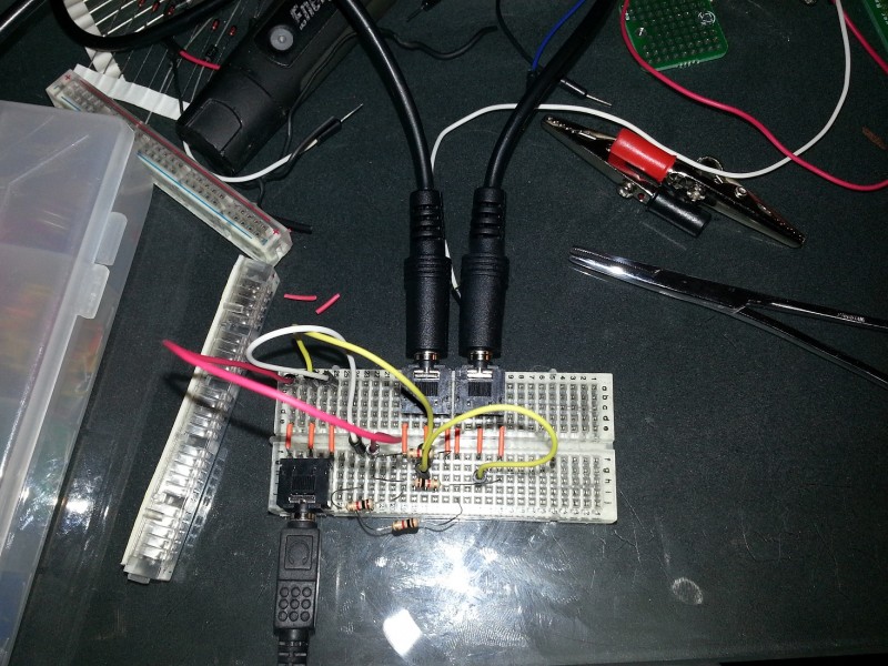
Breadboard Testing

Reverse Audio Splitter Breadboard
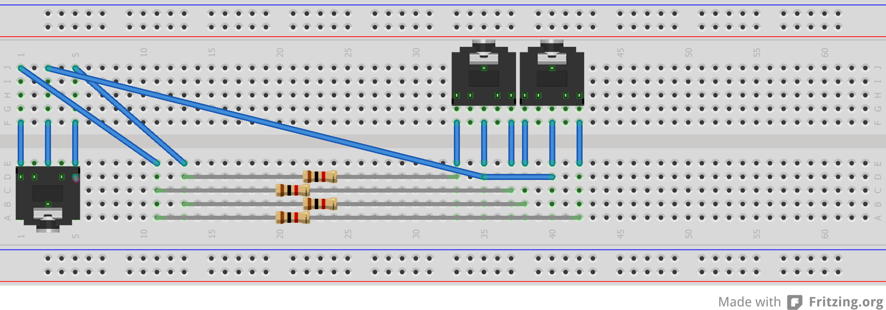
Breadboard Layout
Before building something I wanted to setup a breadboard to test different size resistors and see what would be best for my application. I’ve added two images above regarding the breadboard.
Building The Device
So after testing and deciding on using the 1k resistor it’s time to build the actual device and solder everything together. To do this I used some spare boards I had and just connected everything but in a lot smaller form factor. There are a couple things to keep in mind when doing this. First, make sure all grounds are connected. In my case the ground pin was the center one on the headphone jacks, with the left and right channel being the outside pins. After connecting the grounds, you can connect the left and right channels to the output and just make sure you have a resistor for EACH input device. So in my case, I used a total of 4 resistors. Instead of using 3 headphone jacks I only used 1 and directly connected two audio cables. I then used what is called “Polymorph” to create a “casing” around the board.
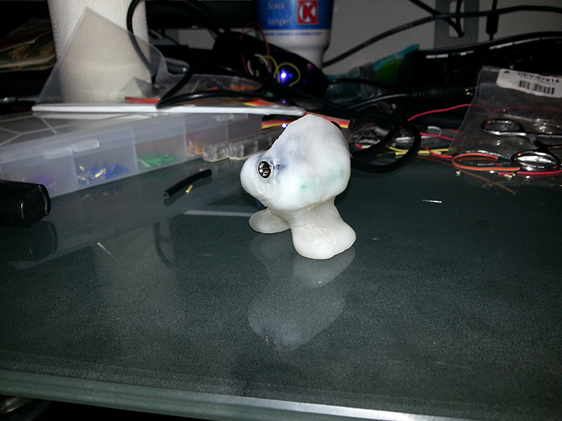
There are some pictures below, as you can see you can get creative with the Polymorph and it’s really easy to form it to whatever you would like. The second picture I created a sort of “fish” with legs but then reverted back to a block type look with a small holder.
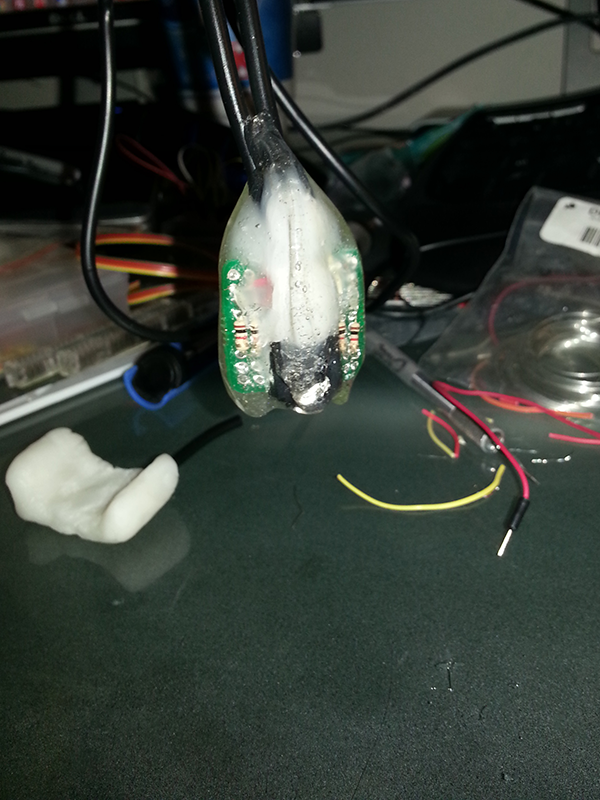
Polymorph Before Hardening

- Polymorph With Legs
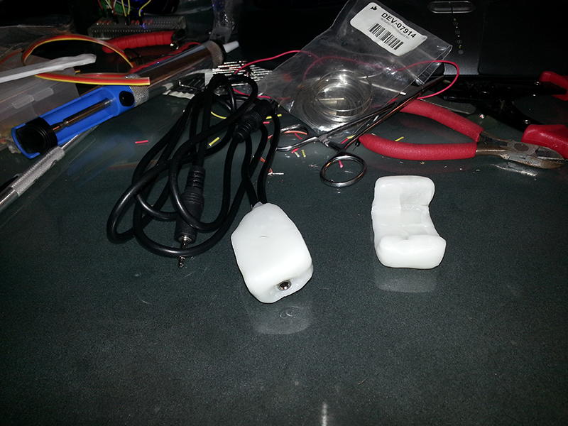
Polymorph With Holder

fixed h-stats.sh